The railway sector of the Institute Mihajlo Pupin is committed to offering top-quality products and solutions and excellent services. The product range meets the railway requirements to improve safety and security at the highest level and to minimize implementation and maintenance costs at the same time. Our products axle counter – BROS and LED signals have the Highest Safety Integrity Level SIL4.
The Institute is highly experienced in integrating, installing, and maintaining the signaling-safety and telecommunication equipment designed to meet the needs of different railways and other large systems. We successfully solve interfaces between different producers and equipment. We have been integrators with world-renowned companies such as Alstom, Bombardier, CRSC on many projects, such as Pančevo station with Alstom interlocking SML400 and other stations with SpDrS64 JZ interlocking, Resnik-Valjevo and TPS Zemun projects with company Bombardier, Rakovica-Resnik project with company CCECC, the high-speed railway line between Serbia and Hungary with company CRSC.
IMP provides turnkey solutions in railway signaling, telecommunication, and radio systems, starting from its own design, engineering, development of technical solutions and products, installation, commissioning and maintenance, and after-sales services.

The main railway products are:
UTD is a detector device used for reliable and accurate train wheel detection and designed for simple installation and maintenance. It can operate in parallel with any other rail device enabling infrastructure modernization through regular maintenance (e.g. UTD can operate in parallel with magnetic or any other wheel detector at the same detection point).
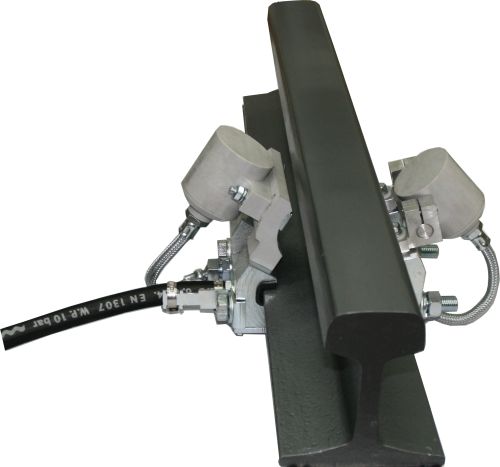
UTD can operate in parallel with any other rail devices enabling infrastructure modernization through regular maintenance (e.g. UTD can operate in parallel with Magnetic or any other wheel detector at the same detection point).
Once installed as a rail crossing detector, at a later stage, it can be integrated into axle counting system, again reducing the cost of section control modernization.
UTD is designed to achieve maximum wheel detection speed of 350km/h.

More information about UTD >>>UTD – EN
Axle Counter BROS is used to control occupancy of the railway sections. The device is placed into a standard 19-inch 3U height rack and it is mounted inside the relay room of the railway station, automatic block system, or level crossing.

Axle Counter BROS uses sensor pairs (SP) at the end of each section and it counts in axles that have entered the section, and counts out axles that have left the section. Sensor pair consists of two sensors (wheel detectors) which are placed next to each other on the rail.
In addition to the basic function of detecting the presence or the arrival of the train wheel, sensor pair also provides detection of the direction and speed of rail vehicles.
Key features

Providing outputs for 8 sections and having up to 12 directly connected sensor pairs, BROS device is perfectly suitable for usage within station interlocking system, as а relatively small number of devices can control all sections of the small, medium or large railway stations.
In the case using BROS for controlling occupancy within automatic signaling block (ABS), only two wires are enough for communication with adjacent axle counters, alternatively optical fiber communication can be used for communication between two BROS devices.
BROS has two modems, which enable communication with maximum two neighboring axle counters, which is important for usage within ABS.
BROS supports all section topologies. Configuration stored in non-volatile memory provides all possible combinations between sensor pairs and relay outputs.
More information about BROS Train Axle Counter >>>>> Axel Counter BROS – EN
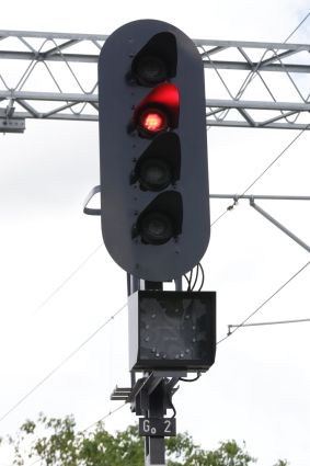
LL-000-m is an LED light source used for main railway signals, designed as a replacement for two filament light bulbs on relay interlocking (SpDrS-64 or Domino55). LL-000-m provides full compatibility with the light bulb interface, i.e. day-time, night-time and blinking operation as well as continuous auxiliary filament test on the red aspect. Due to the complex operating requirements of a relay interlocking, LL-000-m implements a modular and flexible design capable of supporting wide range of operating conditions, applicable on different types of interlocking systems. When used on the SpDrS-64, LL-000-m doesn’t require any modifications on the interlocking system, other than replacing light bulb housing with LL-000-m or replacing just light bulb with LED module.
The main advantage of the LED signal over the incandescent light bulb signal (for SpDrS-64, Domino 55, or any other relay-based interlocking systems) is its considerably longer lifetime and availability which greatly reduces maintenance cost. LL-000-m can also satisfy different electronic interlocking requirements.
This use case proves the advantage of the modular design as it reduces the costs of adapting LL-000-m to different kinds of interlockings. The light source of LL-000-m consists of several individually controlled and monitored high-current LEDs. LL-000-m proves that bulk glass lenses and light bulbs are not necessary. Due to the fact that LL-000-m uses color LEDs, color filters are also not necessary. This also means that color phantom signals are not possible.
This use case was successfully proven on railway infrastructure where around 3000 pcs of LED signals of the Institute Mihajlo Pupin were installed and commissioned on Railway corridor sections.
More information about Railway LED signal >>> Railway LED signals – EN
LED railway indicator signal IND-00 ( IND-01 and IND-02) is developed specifically to provide alphanumeric characters and symbolic drawings, as addition to main railway signal. It can also be used for metro and trams.
Due to the complex operating requirements of a railway relay interlocking, IND-00 implements a modular and flexible design capable of supporting wide range of operating conditions, applicable on different types of relay interlocking systems, too. LED indicators IND1 and IND2 reduces cost of adapting railway indicators to different kind of interlockings.

The basic idea of interlocking system is to secure a safe journey of trains and avoid risk of conflicting movements through an arrangement of tracks such as junctions or crossings. And we, at the Mihajlo Pupin Institute, designed MMI10 – safety HMI (Human Machine Interface) system for administrating, monitoring and controlling one or more railroad interlocking devices. It provides a graphics-based visualization that makes railroad standards compliant with user interface, safe and easy to use at the same time. It’s highly customizable and available in different languages.

Primary function of m2SCD device is implementation of railway signal interlocking on four routes.
Basic configuration of the device supports control and driving of four signal lights and four announcing signals.
Device can be configured to control lower number of entrance routes or expansion for greater number of routes. In that case all descriptions can be expanded on additional entrance routes.
Complete equipment is placed in standard 19“ industrial rack enclosure. Complete device consists of: batteries, battery charger, inverter for signal power supply, axle sensors and logic for signal interlocking and entrance route enabling and clearing.
Control panel is used to set and clear entrance route and to display signal, sensor and system state. Control panel is freely movable and can be placed in the closed or on the appropriate traffic control desk independently from the rack enclosure (this has to be defined in project documentation).
More information >>>>> Mini m2SCD – EN
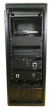
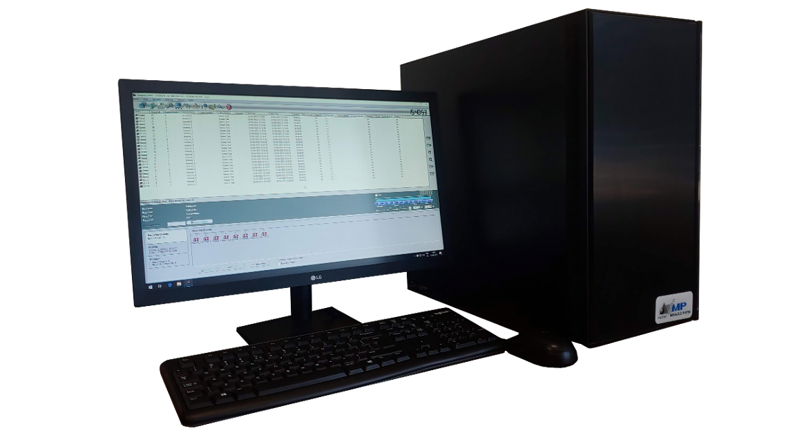
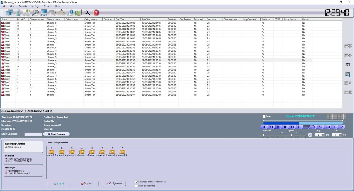
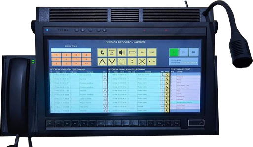
The Registrophone (digital voice recorder) Pupin-Atis VC-MDx is used for recording and archiving conversations between participants on telephone and radio links. It consists of a computer with associated peripherals (keyboard, mouse, monitor, external speakers) and an alarm (external) unit.
In the computer itself, there are interface boards in the form of PCI cards whose basic function is to detect and record traffic on telephone and radio lines. Dedicated software installed on the computer processes recordings that interface boards collect from telephone and radio lines and archive them as such on internal hard drives. This software allows you to listen to conversations that are in progress, those that have already been archived, and to transfer archived
recordings to some permanent memory.
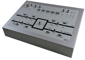
The alarm unit is located at the dispatcher’s desk and its role is to monitor the operation of the registrophone and in the event of any irregularity in the operation of the registrophone audibly and visually inform the dispatcher about the malfunction.
The registrophone computer is in the form of a standard desktop housing with associated peripherals (keyboard, mouse, monitor, external speakers), and is mounted within the railway station room where telephone and radio connections used by the dispatcher in daily work are located.
The registrophone can record and archive up to 256 telephone or radio channels. Telephone and radio connections that are recorded are routed from the terminal block with the cable to the 50-pin connector on the registrophone interface boards. The recordings on the registrophone can be accessed locally and remotely (provided there is a LAN connection between the registrophone and the client computer with the appropriate software).
More information on: Registrophone – EN
The railway radio dispatch system is used for the transmission of speech and commands between the rail vehicle and the radio dispatch center. The system
consists of a dispatch center, fixed railway radio base stations deployed along the rail, a modulation line, and mobile radio stations located in rail vehicles.
In the existing analog system, the connection between the dispatch center and the fixed radio stations is wired, while the connection between the fixed and mobile radio stations is wireless, realized by radio waves. The modulation line can be with optical fiber or may be a four-wire connection, where one pair is used to send information in the direction from the dispatch center to the rail vehicles, while the other pair is used to send information in the direction from the rail vehicle to the dispatch center.
The digital radio dispatch center (D-RDC) is designed to be fully compatible with the existing analog dispatch center by supporting all currently used services with the possibility to easily add new ones. This enables easy replacement of existing analog dispatch center with the new D-RDC systems, without any modifications done on modulation lines, fixed railway radio stations, and mobile radio stations in rail vehicles.
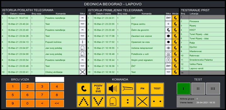
The entire manipulation of the D-RDC system is performed through the dispatch control panel. The control panel allows you to view the history of sent commands, and the history of received notifications, to send commands to the rail vehicle, to receive notifications from the rail vehicle, initiate calls to the rail vehicle, and receive calls from the rail vehicle, as well as to test fixed radio base stations.
More information: Railway D-RDC System – EN
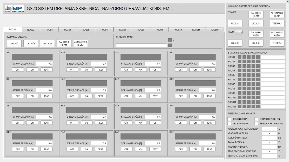
The GS20 point heating system is based on a flexible architecture and can be adapted to any design requirement and any topology. This system can be centralized, decentralized, autonomous, or integrated into a centralized monitoring and control system.
GS20 System is powered from the Overhead contact line by pole-mounted substations or some other alternative power source. The system itself includes HMI workstation, SCADA subsystem, distribution cabinets, connection cabinets, electric heaters, and electrical cables for connection, control, and signaling. It is designed for easy handling and easy fault detection.

The system is designed so that tests can be performed to check and determine the failures of individual heaters.
The heaters are switched on, in normal operation, sequentially one after the other with a predetermined delay, in order to reduce the load on the electrical network.
The current state of the system can be monitored at the HMI workstation in the traffic office of the train dispatcher, and any irregularities are further highlighted. PLC controllers installed in each distribution cabinet communicate with the control system. The heater is switched on according to the relay command principle in order to reduce electric shocks and network load.
More information: Station point heating system – GS20 – EN