
Research Topic: Intelligent Navigation of Mobile Robots in Working Environments
Autonomous intelligent navigation is a major research issue which would affect robotic systems in near future. Safe navigation is a core skill these robots must have in order to be able to deploy new technologies to the mass market. In order to navigate, a robot has to create a map of the environment, be able to locate itself on the map, and plan safe trajectories on it. It also has to be able to avoid obstacles on its way to the goal as they appear. It is assumed that all obstacles are static and that their position is known. Many algorithms have been proposed, such as road maps, potential fields, mathematical programming, etc. Unfortunately, these algorithms are computationally too complex to be implemented in real time. The algorithms of soft computing could also be used, such as particle swarm optimization. In this research, PSO algorithm is used. PSO represents multi-agent search technique, which is based on simplified social behavior of large animal groups. It has been proven that in many cases PSO algorithm provides fast and efficient solution of optimization problem.
The goal is generating collision free path from starting to destination point, so that the path is as short as possible. Generating path is given as array of two-dimensional points, so the obtained path is not smooth. Robot has fixed maximum step size, i.e maximum distance between current and next point . Increase of this parameter speeds up the algorithm, but decreases the path smoothness. It is also assumed that all obstacles are circular and there is no overlapping between obstacles.
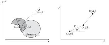
Fig. 1. Search region of PSO algorithm
Algorithm has stochastic nature, so it will not give the same result if it proceeds from start to destination point and in reverse direction. So algorithm must proceed in both directions, and choose shorter path.
Path interpolation using RBFNN
Path interpolation is performed using RBFNN with one input (time) and two outputs (x and y coordinate of path point). For this purpose, some other types of neural networks can be used, but in this case RBFNN gives very good results, accurate approximation and fast training.
The first step is generation of training set. This means that time instant must be associated with every point on the path. Simple networks cannot approximate path adequately, while too complex networks can be sensitive to noise presence.
Trajectory generation based on interpolated path
Trajectory generation based on given path means introduction of time. i.e. trajectory represents time-parameterized path. The simplest way of trajectory generation is adoption of uniform velocity of motion along the path. But the goal is achievement of variable velocity of motion, such that robot moves fast on straight segments of the path and slow in curves, i.e. robot velocity should be inversely proportional to path curvature. At the beginning robot should accelerate uniformly, until it reaches the desired speed and slow down uniformly, at the end of the motion.
Fig. 2. Illustration of method of curvature determination.
Design of tracking controller
Structure of control system is shown on Fig.3. Simple proportional controller is used as a tracking controller. Controller should generate control action which directs robot to the desired trajectory, as shown on Fig. 4.
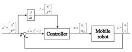
Fig. 3. Structure of control system.
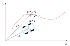
Fig. 4. Principle of system inputs generation.
As can be seen, velocity correction is chosen as nonlinear function of error vector between desired and achieved position, i.e. dead zone around desired point is introduced. Introducing nonlinearity is necessary, because it doesn’t allow oscillations of robot position when robot comes close enough to it. Dead zone changes its size depending on desired velocity, i.e. it decreases when desired velocity increases. As can be seen from above equations, controller generate velocity vector that directs robot to the desired trajectory. This velocity is used for evaluation of system inputs, i.e. left and right wheels’ angular velocities.
Fig. 5. Paths generated by PSO algorithm.
Fig. 6. Interpolated path using RBFNN.
Fig. 7. Velocity profile, error plots and plots of (x, y) coordinate and heading angle q versus time.
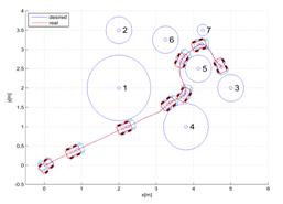
Fig. 8. Trajectory tracking performance of mobile robot controlled by proportional controller.