MSHUB-3D
MSHUB-3D is a customized software interface (developed in MATLAB engineering tool) dedicated for enhanced 3D-sensing, modeling and simulation of human bio-mechanics. MSHUB-3D is complement to the marker-based capture motion systems to interpret and analyze experimentally measured data obtained from the CMS (e.g. VICON-460) and to map captured motion to the space of anthropomorphic models of human body locomotion. MSHUB-3D enables satisfactory accurate modeling and simulation of the anthropomorphic kinematics and dynamics based on the experimentally acquired data from the CMS (Fig. 1).
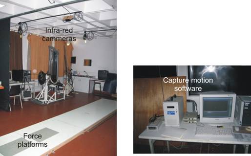
Fig. 1. Capture motion studio equipped with VICON-460 system – 6 infra-red cameras, 2 force platforms and host-computer with capture motion software (CURAPS, University of Reunion, Le Tampon, France).
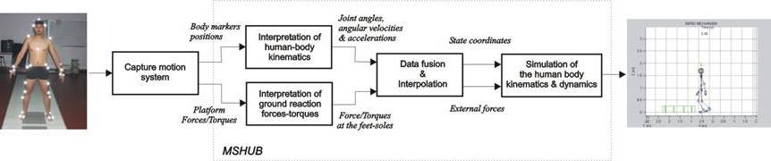
Fig. 2. Block-schema of identification of human body kinematics and dynamics based on the acquired, experimental capture motion data.
CMS generates as output two kinds of files: a) Descartes coordinates (X, Y, Z) of body markers with sampling frequency for example of 100 or 200 [Hz] and, b) ground reaction forces and torques captured by two force platforms (Fig. 1) with 1 GHz of frequency of sampling. Both data sets can be exported in some of the appropriate file formats (ASCI text or MS Excel) suitable for processing in some of the text-editors. The obtained files are used by MSHUB-3D interface for processing, interpretation and analysis, and finally for mapping to the appropriate kinematical and dynamical models and simulation. The block scheme presenting the process from capturing data about the human-body motion to its enhanced modeling and simulation is presented in Fig. 2.
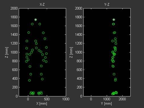
The body markers, during the capture motion experiments, should be attached to the body of the patient strictly in a way presented in Fig. 3 in order to enable proper operation of the MSHUB-3D processing modules.
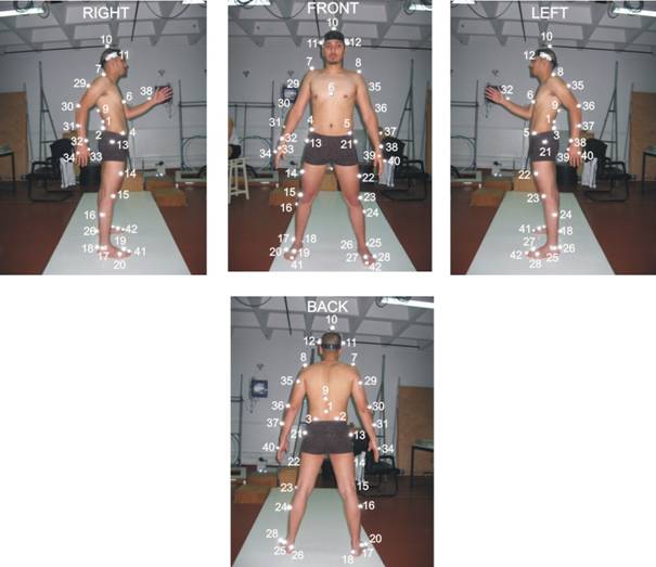
Fig. 3. Appropriate body markers distribution arranged for the bio-mechanical measurements of human locomotion (CURAPS, University of Reunion, Le Tampon, France).
The principle idea of body motion reconstruction is in fact that the body markers are grouped into the particular triangular contours, rotating relatively one to each other. In such a way, markers arranged, enable determination of the relative angular displacements (roll, pitch and yaw) around the coordinate axes X, Y and Z between the neighbor body limbs/links. Due to this fact, the markers, belonging to the same limbs, must not be set to be co-linear! There are two setups of markers used in experiments and processed in the MSHUB-3D: (i) 42-markers setup, and (ii) 40-markers setup. The former has two markers more (41, 42, see Fig. 3) for the feet toes. Regardless to the setup to be chosen, the position of the body-markers should track the arrangement of markers as it is presented in Fig. 3 with rather small tolerance of positioning concerning relative positions of the markers within the triangular contours.
CMS software, presented in Fig. 2, generates at its output two files: a) file with data-samples (100 or 200 Hz) of the Descartes coordinates of body markers during motion, and b) corresponding file of forces/torques acting to the platforms centers, measured with 1 GHz of frequency of sampling. Both files are exported from the CMS in the standard formats (ASCI or Excel) suitable for further processing by use of the MSHUB-3D as shown in Fig. 2.
Picture Gallery - Simulation & Experimental Results